What Is Expansion Valve ?

The expansion valve is situated in the liquid line between the condenser and the inlet of the evaporator.This is one of the basic components of the refrigeration system which are used to control refrigerant flow.It reduce the pressure & temperature of the refrigerant coming from the condenser as per the requirement of the system. And also helps to regulate the flow( Metering ) of refrigerant as per the load on the Evaporator.
Expansion valves do not directly control the evaporation temperature. Instead, they regulate the superheating by adjusting the mass flow of refrigerant into the evaporator, and maintain the pressure difference between the highpressure and low-pressure sides. The evaporation temperature depends on the capacity of the compressor and the characteristics and efficiency of the evaporator.
The term "low side" is used to indicate part of the system that acts under low pressure, in this case evaporator. high side is used to indicate part of the system that works under high pressure, in this case the condenser.
Basically Two types of expansion devices :-
1.Variable Restriction Type.
2. Constant Restriction Type.
1.Variable Restriction Type :-
AUTOMATIC EXPANSION VALVE :-
FLOAT VALVE :-
The float valve starts with the floating float in the liquid refrigerant. Low-side float and upper side-float are used to control flow of fluid refrigrants.
The lower side float helps to maintain continuous levels of liquid condensation in the evaporator. It opens when there is no fluid in externality. And when the vapor is liquid, it closes.The upper side is located next to the high pressure system of the float and keeps the condenser continuously in the refrigeration. When the compressor is operated, the condensed refrigeration flows into the float chamber and opens the valve.
This divides the refrigerant into evaporator where it is stored. As the liquid level comes in the float chamber, the valve will prevent the opening of the trail to turn the flow towards evaporation.
CAPILARY TUBES :-
Capillary tubes are the simplest of all refrigerant flow controls, and it is a is a fixed restriction type device with no moving parts. They normally consist only of a copper pipe, diameter 0.5 to 1.5 mm and length 1.5 to 6 m.It is along and narrow tube connecting the condenser directly to the evaporator.Its resistance to flow permits the capillary to be used as as pressure reducing device to meter the flow of refrigerant given to the Evaporator.

Capillary tubes can be found on small, high-volume commercial systems such as household refrigerators, but can also be used for larger systems if the operating conditions are relatively stable. The capillary tube is vulnerable to clogging, which is why a filter drier and filter are normally mounted before the inlet.
The low-pressure side of a refrigerant system with a capillary expansion device must be able to hold the whole refrigerant charge. When the compressor stops, the refrigerant will migrate to the cold, low-pressure side. Often, the low-pressure side is equipped with a liquid separator, which acts as a receiver, just before the compressor.
The refrigerant charge must also be carefully considered for capillary tube systems. An overcharged system will back up condensate into the condenser. This will eventually flood the condenser totally if the overcharge is sufficiently large or if there is a large change in operating conditions. Undercharge, on the other hand, will result in starvation of the evaporator, with hunting as a result.
The advantage of a capillary tube are its simplicity , low cost and the absence of any moving parts. The disadvantages associated with this device is that the refrigerant must be free from moisture and dirt otherwise it will choke the tube and stop the flow of refrigerant. It cannot e used with high fluctuating load conditions.

The expansion valve is situated in the liquid line between the condenser and the inlet of the evaporator.This is one of the basic components of the refrigeration system which are used to control refrigerant flow.It reduce the pressure & temperature of the refrigerant coming from the condenser as per the requirement of the system. And also helps to regulate the flow( Metering ) of refrigerant as per the load on the Evaporator.
Expansion valves do not directly control the evaporation temperature. Instead, they regulate the superheating by adjusting the mass flow of refrigerant into the evaporator, and maintain the pressure difference between the highpressure and low-pressure sides. The evaporation temperature depends on the capacity of the compressor and the characteristics and efficiency of the evaporator.
The term "low side" is used to indicate part of the system that acts under low pressure, in this case evaporator. high side is used to indicate part of the system that works under high pressure, in this case the condenser.
Basically Two types of expansion devices :-
1.Variable Restriction Type.
2. Constant Restriction Type.
1.Variable Restriction Type :-
In this, the extent of opening area of flow keeps on changing depending on the type of control. Three common types are :-
A. Automatic Expansion Valve (Pressure Control ).
B. Thermostatic Expansion Valve.
C. Float Valves.
i) High side Float valve In this it maintains the liquid at a constant level in the condenser.
ii) Low side Float valve In this maintains the liquid at constant level in the Evaporator.
2. Constant Restriction Type :-
Capillary Tube in which it is merely along tube with a narrow diameter bore.
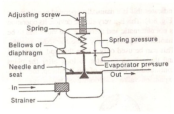
AUTOMATIC EXPANSION VALVE :-
The Automatic Expansion valves works in response to the pressure changes in the evaporator due to
increase in load( pressure increase) or due to decrease in load( pressure
decreases).This valve maintains a constant pressure throughout the varying load on
the evaporator controlling the quantity of refrigerant flowing into
Evaporator.It consists of a needle valve, a seat, a diaphragm and a spring as shown in
figure.
The opening of the valve in the seat is controlled by the two opposing forces.
A. the tension in the spring
B. The pressure in the evaporator acting on diaphragm.
Once the spring is adjusted for a desired evaporator pressure and given load, then the valve operates automatically with changing load conditions in the evaporator.
Assume the spring is adjusted initially to maintain a pressure of 1.5 bar in the evaporator at a given load. If the pressure falls below 1.5 bar due to decrease in load, the spring pressure will exceed the evaporator pressure and causes the valve to open more and increases the flow of refrigerant. If the pressure in the evaporator increases due to increase in load above 1.5 bar, the evaporator pressure will exceed the spring tension and valve move in closing direction. This reduces the quantity of refrigerant flow in the evaporator
THERMOSTATIC EXPANSION VALVE :-
Thermostatic expansion valve uses the valve system to control the flow of liquid condensation in evaporative coils. The flow is controlled by pressure in the evaporator.
This type of metering device can work well when the load fluctuates and therefore is suitable for use in the air conditioning system. When the evaporator heats the valve, the high flow rate gives AMD when it cools down, it reduces the rate of flow.
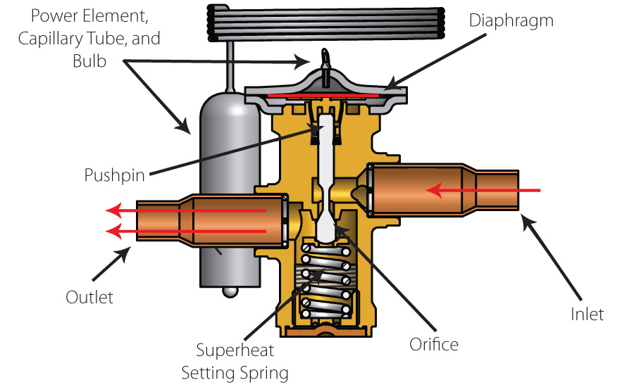
It is also generally referred to as TXV, TEV or TX valve. There is a sensing bulb that detects the coil temperature and is usually located at high temperatures inside the evaporation.
To ensure proper sensing, the bulb must be clamped on the suction line. When the temperature of the evaporator increases due to the demand for cooling, the pressure in the bulb will also increase so that the spring is forced to open the valve.
when the temperature of the evaporation decreases due to lack of cooling demand, the bulb pressure will snap so that the spring causes the valve to close.
The opening of the valve in the seat is controlled by the two opposing forces.
A. the tension in the spring
B. The pressure in the evaporator acting on diaphragm.
Once the spring is adjusted for a desired evaporator pressure and given load, then the valve operates automatically with changing load conditions in the evaporator.
Assume the spring is adjusted initially to maintain a pressure of 1.5 bar in the evaporator at a given load. If the pressure falls below 1.5 bar due to decrease in load, the spring pressure will exceed the evaporator pressure and causes the valve to open more and increases the flow of refrigerant. If the pressure in the evaporator increases due to increase in load above 1.5 bar, the evaporator pressure will exceed the spring tension and valve move in closing direction. This reduces the quantity of refrigerant flow in the evaporator
THERMOSTATIC EXPANSION VALVE :-
Thermostatic expansion valve uses the valve system to control the flow of liquid condensation in evaporative coils. The flow is controlled by pressure in the evaporator.
This type of metering device can work well when the load fluctuates and therefore is suitable for use in the air conditioning system. When the evaporator heats the valve, the high flow rate gives AMD when it cools down, it reduces the rate of flow.
It is also generally referred to as TXV, TEV or TX valve. There is a sensing bulb that detects the coil temperature and is usually located at high temperatures inside the evaporation.
To ensure proper sensing, the bulb must be clamped on the suction line. When the temperature of the evaporator increases due to the demand for cooling, the pressure in the bulb will also increase so that the spring is forced to open the valve.
when the temperature of the evaporation decreases due to lack of cooling demand, the bulb pressure will snap so that the spring causes the valve to close.
FLOAT VALVE :-
The float valve starts with the floating float in the liquid refrigerant. Low-side float and upper side-float are used to control flow of fluid refrigrants.
The lower side float helps to maintain continuous levels of liquid condensation in the evaporator. It opens when there is no fluid in externality. And when the vapor is liquid, it closes.The upper side is located next to the high pressure system of the float and keeps the condenser continuously in the refrigeration. When the compressor is operated, the condensed refrigeration flows into the float chamber and opens the valve.
This divides the refrigerant into evaporator where it is stored. As the liquid level comes in the float chamber, the valve will prevent the opening of the trail to turn the flow towards evaporation.
CAPILARY TUBES :-
Capillary tubes are the simplest of all refrigerant flow controls, and it is a is a fixed restriction type device with no moving parts. They normally consist only of a copper pipe, diameter 0.5 to 1.5 mm and length 1.5 to 6 m.It is along and narrow tube connecting the condenser directly to the evaporator.Its resistance to flow permits the capillary to be used as as pressure reducing device to meter the flow of refrigerant given to the Evaporator.
Capillary tubes can be found on small, high-volume commercial systems such as household refrigerators, but can also be used for larger systems if the operating conditions are relatively stable. The capillary tube is vulnerable to clogging, which is why a filter drier and filter are normally mounted before the inlet.
The low-pressure side of a refrigerant system with a capillary expansion device must be able to hold the whole refrigerant charge. When the compressor stops, the refrigerant will migrate to the cold, low-pressure side. Often, the low-pressure side is equipped with a liquid separator, which acts as a receiver, just before the compressor.
The refrigerant charge must also be carefully considered for capillary tube systems. An overcharged system will back up condensate into the condenser. This will eventually flood the condenser totally if the overcharge is sufficiently large or if there is a large change in operating conditions. Undercharge, on the other hand, will result in starvation of the evaporator, with hunting as a result.
Comments
Post a Comment